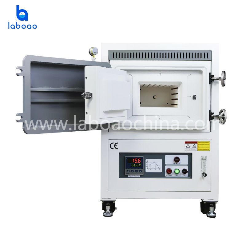
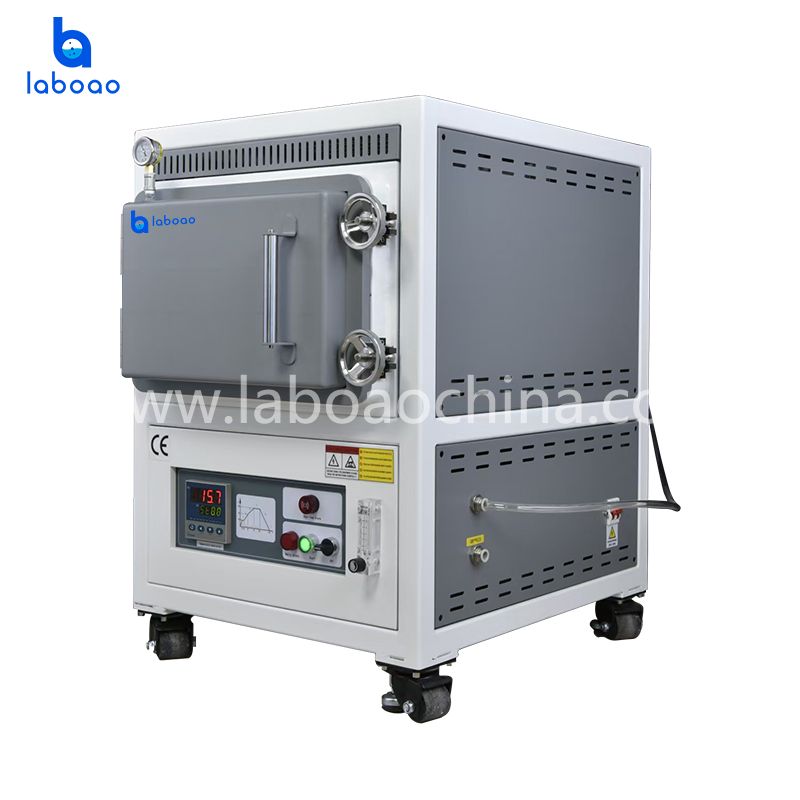
Features And Installation Tips For Box-Type Resistance Furnaces
I. Scope of Application:
(1) Cement and Construction Materials Industry: Used for the thermal processing or treatment of small workpieces.
(2) Pharmaceutical Industry: Used for pharmaceutical testing and the pretreatment of medical samples.
(3) Analytical Chemistry: Used for sample preparation in fields such as water quality analysis and environmental analysis; also applicable to petroleum analysis.
(4) Coal Analysis: Used for determining moisture, ash content, volatile matter, ash fusion temperature, ash composition, and elemental composition. It can also serve as a general-purpose ashing furnace.
II. Product Features:
Chamber: Constructed from specialized ceramic fiber materials, ensuring rapid heating and excellent thermal insulation.
Heating Elements: Electric heating wires for 1000°C and 1200°C models; silicon carbide rods for 1300°C and 1400°C models; and molybdenum disilicide (silicon-molybdenum) rods for 1600°C and 1700°C models.
Temperature Control System: Employs thyristor (SCR) control with PID parameter auto-tuning, as well as compensation and calibration functions.
Safety: Includes a password-locking feature for secure and reliable operation.
III. Installation and Use:
1. After unpacking, inspect the box-type resistance furnace to ensure it is intact and that all accessories are included. Generally, these furnaces do not require complex installation; they simply need to be placed on a level floor or a stable shelf indoors. The controller should be protected from vibration and positioned away from the electric furnace to prevent internal components from malfunctioning due to excessive heat.
2. Insert the thermocouple 20–50 mm into the furnace chamber, and seal the gap between the opening and the thermocouple using asbestos rope. Use compensating lead wires (or insulated steel-core wires) to connect the thermocouple to the controller, ensuring the positive and negative terminals are correctly aligned—do not reverse them.
3. Install a separate power switch at the power supply input to control the main power. To ensure safe operation, both the electric furnace and the controller must be reliably grounded.
4. Before use, adjust the temperature indicator to its zero point. If using compensating lead wires and a cold-junction compensator, set the mechanical zero point to the reference temperature of the cold-junction compensator. If no compensating lead wires are used, set the mechanical zero point to the zero mark; in this case, the indicated temperature represents the difference between the measurement point and the cold junction of the thermocouple.
5. After verifying that all wiring is correct, replace the controller housing. Set the pointer on the temperature indicator to the desired operating temperature, then connect the power. Turn on the power switch; the green light on the temperature indicator will illuminate, the relay will engage, the furnace will receive power, and the ammeter will show a current reading. As the temperature inside the furnace rises, the pointer on the temperature indicator will also move upward, confirming that the system is functioning properly. The heating and temperature-maintenance phases are indicated by the green and red lights on the temperature indicator: the green light signifies heating, while the red light signifies that the target temperature has been reached and is being maintained.
PreviousOperating Instructions And Precautions For Benchtop Sterilizers
NextCauses And Solutions For Insufficient Pressure In Circulating Water Vacuum Pumps